MIL-DTL-3124E(SH)
3.3.11.7 Generators with frame sizes not less than 200 kilowatts at 1800 r/min and all generators using bus bar
in lieu of cable. Terminal boards need not be provided. The leads shall be clamped into position so that strain from
the outside cannot be transmitted to the connections within the generator frame. The leads shall be of sufficient
length to facilitate making connections and shall be provided with a means for making connections to the ship
cables. Terminal lugs shall not be provided.
3.3.11.7.1 Bus bar leads. Bus bar leads shall be in accordance with 3.3.11.3.
3.3.11.8 Terminal markings. When facing the opposite drive end, terminals shall be marked T1, T2, T3
reading from front (the end opposite the drive) to back, right to left, or top to bottom. Direct current (DC) field leads
shall be marked F1 and F2. A labeled schematic vector placard shall be mounted on the generator, showing
inverted-wye windings or delta windings, as appropriate.
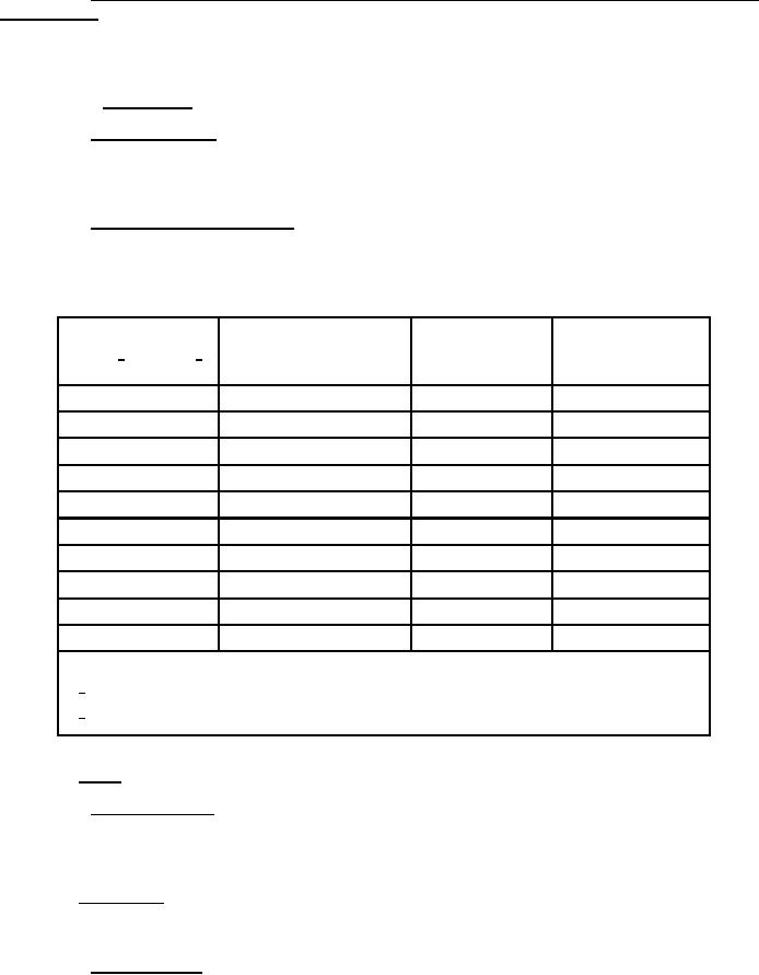
3.3.11.9 Minimum radius of cable bend. The location of connections and clearances shall be such that
specified cable can be installed using the minimum radius of bend in accordance with MIL-DTL-24643. As
construction design guidance, Type LSTSGU cable in accordance with MIL-DTL-24643/16 is shown for selected
size cables, with recommended current-carrying capacities and minimum radius of bend:
Current rating
Cable overall
Minimum allowable
Wire size,
(amperes) at
maximum
radius for cable
MCM 1/ or AWG 2/
60 Hz and 122 °F (50 °C)
diameter (inches)
bend (inches)
16
10
0.411
3.5
14
17
0.449
3.5
10
36
0.575
4.5
9
47
0.718
5.5
7
64
0.812
6.5
3
101
0.969
8.0
1
136
1.134
9.0
000
216
1.515
12.0
300
320
1.957
15.5
400
400
2.203
17.5
NOTES:
1/
MCM is the old abbreviation for one thousand circular mils.
2/
AWG is the abbreviation for American wire gauge.
3.3.12 Frame. The frame shall be of rigid construction, either integral with the support structure or detachable.
3.3.12.1 Detachable frames. Detachable frames shall have feet large enough to accommodate holding-down
bolts, dowel pins, and jackscrews, where used, to ensure attachment to the common bedplate or to the structural
foundations of the vessel, as required. The frame feet shall be machined and drilled for holding-down bolts. Fitted
bolt holes shall be left with an allowance for reaming at time of installation of generator with prime mover.
3.3.13 End brackets. Where end brackets are used, a machined shoulder joint shall be provided between the
frame and the end brackets. End brackets shall be secured to the frame by not less than four hexagon-head bolts or
cap screws of suitable size and strength.
3.3.13.1 Resilient gaskets. Resilient gaskets shall not be placed between any bearing support members and the
frame.
10
For Parts Inquires call Parts Hangar, Inc (727) 493-0744
© Copyright 2015 Integrated Publishing, Inc.
A Service Disabled Veteran Owned Small Business