MIL-DTL-3124E(SH)
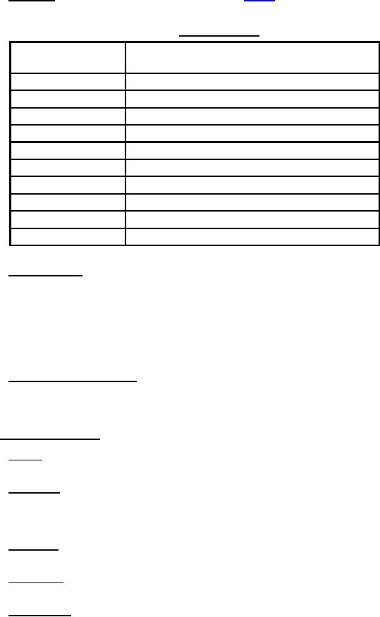
3.3.8.1.2 Clearances. Bearing clearances shall be as specified in table II.
TABLE II. Bearing clearances.
Basic diameter of
Maximum design diametrical bearing clearance,
journal (inches)
including shaft and bearing tolerances (inch)
1.000
0.004
2.000
0.005
3.000
0.007
4.000
0.009
5.000
0.010
6.000
0.012
7.000
0.014
8.000
0.016
9.000
0.018
10.000
0.020
3.3.8.1.3 Bearing housings. For forced lubricated systems, the housing shall prevent the escape or migration of
oil and oil-laden vapor along the shaft and split line by maintaining a positive pressure in the bearing cavity under
operating conditions. The use of felt and friction type seals shall be prohibited. Provision shall also be made to
ensure against the suction of oil vapor into the interior of the generator or externally mounted components, that is,
permanent magnet alternator, slip rings, brushless exciter, and so forth. Where resistance temperature indicators
(RTEs) are not provided, a tapped hole shall be provided for insertion of a thermometer into the bearing and bearing
shell for bearing temperature observation. These observation openings shall be made oiltight by a cover secured by
screws, screw plugs, or equivalent means.
3.3.8.1.4 Oil-filling and level indicators. Where forced lubrication is not used, an opening or standpipe for
filling, for preventing overfilling, and for indicating the oil level shall be provided in the reservoir and shall be fitted
with an oiltight plug or cap to prevent the escape of oil when the generator is subject to the inclination specified in
3.3.8.2 Ball and roller bearings. Ball and roller bearings shall be as specified in 3.3.8.2.1 through 3.3.8.2.8.
3.3.8.2.1 General. When used, ball and roller bearings shall be in accordance with an ANSI/ABMA Dimension
Series.
3.3.8.2.2 Grease cups. Compression grease cups of steel shall be used on generators where grease is used for
lubrication. The grease cups shall be preferentially placed on top of the bearing housing unless another location is
required to ensure optimal distribution of grease as determined by the manufacturer. Grease shall be in accordance
with DOD-G-24508.
3.3.8.2.3 Drain plugs. Accessible drain plugs shall be provided in locations to afford maximum purging of
grease during regreasing.
3.3.8.2.4 Grease pipes. Extension grease pipes shall provide accessibility for grease cups and drain plugs. The
use of extension grease pipes is permitted in order to provide accessibility to grease cups and drain plugs.
3.3.8.2.5 Axial end play. A 0.020-inch minimum axial clearance between the opposite shaft extension end
bearing outer race and housing shoulder shall be provided for shaft thermal expansion. Axial movement of the shaft
shall be not greater than 0.040 inch including bearing end play.
8
For Parts Inquires call Parts Hangar, Inc (727) 493-0744
© Copyright 2015 Integrated Publishing, Inc.
A Service Disabled Veteran Owned Small Business